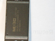
Dismantling the F2-425Plus
Posted: 05 Aug 2026, 23:43
WHY On Earth?: Much like the chicken; to see what is on the other side - or, more precisely, to see what the USB-DOM looks like and to take some measurements. (Take all necessary precautions for handling electronic components!!)
1. Remove the 2 screws in the base. (There are videos on YouTube for the basic stuff.)
2. Slide the outer case off the chassis (The Nvme slots are exposed. The USB-DOM is on the other side of the motherboard.
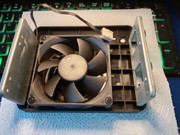
3. Remove the rear panel containing the fan.
3a. Remove 2 screws each side where the rear panel supports are attached to the chassis:
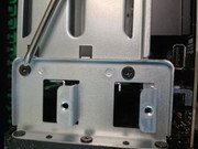
Watch out for the fan wire wrapped around the leg of the support. Good news - the fan connector is a "proper" 4-pin connector. Disconnect the fan connector.
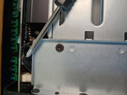
Slide the fan assembly away from the chassis.
4. Remove the motherboard.
4a. Remove the 4 screws holding the motherboard to the chassis.
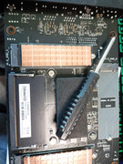
4b. Carefully lift the motherboard from the chassis. I found it best to start lifting from the end opposite the front panel. It is necessary to slightly tilt in order to clear the front panel and the SATA riser has to disconnect from the motherboard as well. Once the riser disconnects, lift the motherboard clear.
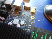

As all the good books say "assembly is the reverse of the foregoing". But, NOTE:
Ensure that the SATA riser connects properly with it's motherboard socket.
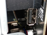
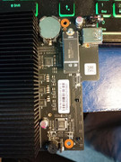
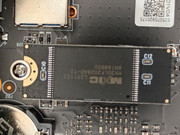
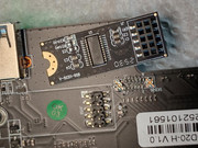
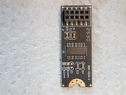
Images relating to USB-dom follow.
1. Remove the 2 screws in the base. (There are videos on YouTube for the basic stuff.)
2. Slide the outer case off the chassis (The Nvme slots are exposed. The USB-DOM is on the other side of the motherboard.
3. Remove the rear panel containing the fan.
3a. Remove 2 screws each side where the rear panel supports are attached to the chassis:
Watch out for the fan wire wrapped around the leg of the support. Good news - the fan connector is a "proper" 4-pin connector. Disconnect the fan connector.
Slide the fan assembly away from the chassis.
4. Remove the motherboard.
4a. Remove the 4 screws holding the motherboard to the chassis.
4b. Carefully lift the motherboard from the chassis. I found it best to start lifting from the end opposite the front panel. It is necessary to slightly tilt in order to clear the front panel and the SATA riser has to disconnect from the motherboard as well. Once the riser disconnects, lift the motherboard clear.
As all the good books say "assembly is the reverse of the foregoing". But, NOTE:
Ensure that the SATA riser connects properly with it's motherboard socket.
Images relating to USB-dom follow.